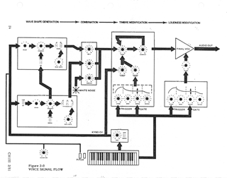
 Fig
2-0
Fig
2-0[The Sequential Circuits Pro-One Annotated Manual]
[Annotations in bold square brackets by
jet.]
[Scanned from a photocopy of the original. Original format retained
wherever possible.]
[Modified or replaced graphics noted as such.]
|
SECTION 2 |
FRONT PANEL |
|
|
2-0 |
13 | |
|
2-1 |
13 | |
|
2-2 |
15 | |
|
2-3 |
16 | |
|
2-4 |
17 | |
|
2-5 |
17 | |
|
2-6 |
18 | |
|
2-7 |
20 | |
|
2-8 |
20 |
This section explains the "modules" outlined on the front panel. The front panel is divided into "voice" and "modulation" sections. The basic voice is discussed first, then modulation. Signal flow, the alternatives of each switch, and ranges of each knob are described.
As an analog voltage-controlled synthesizer voice, the Pro-One can be understood at its most general level in terms of three functions: audio waveshape generation, modification, and control.
Figure 2-0 diagrams voice signal flow. As mentioned above (About the Pro-One), OSC A and OSC B are the principal sound generators. They are supplemented by the NOISE source (for unpitched sounds such as "surf") or an external audio input which bypasses the NOISE source. (To learn how to use the external audio input, see paragraph 3-1.)
The MIXER is a modifier. It sets OSC A, OSC B, and NOISE (or EXT audio) levels and combines them into one signal which enters the FILTER. The FILTER also functions normally as a modifier, by cutting off the high-frequency components of input audio signals. However, by feeding a sufficient amount of FILTER output back to its input with the RESONANCE control, the FILTER will become a pitch generator at its CUTOFF frequency.
The AMPLIFIER stage is also a modifier because it raises or lowers the signal level from the FILTER to the external power amplifier and speaker. The AMPLIFIER is controlled by its own envelope generator and the VOLUME control, which attenuates the generator's control voltage output, reducing the overall output level.
OSC A, OSC B, the FILTER, AMPLIFIER, and envelope generators are all voltage controlled. Mechanical devices such as the keyboard, switches, knobs and wheels form one group of controllers. The other group is electronic, consisting of the LFO, OSC B, and FILT ENV modulation sources. The term "modulation" refers to a periodic or consistent (as opposed to random) aural change which is interesting or musically useful. Modulation is created with electronic controllers when it is not possible to adjust a mechanical controller with the required speed or precision. Electronic controllers free the hands for other uses.
The keyboard is the most conspicuous controller. It issues a CV which increases as you play upwards from CO to C3. This keyboard control voltage (KYBD CV) always
CM 1 00B 5/8
[Image rotated 90 degrees CW]
[Page 15]
controls OSC A's frequency, and controls OSC B frequency if the OSC B KYBD switch is on. The KYBD CV also controls the FILTER CUTOFF frequency to the extent the FILTER KEYBOARD AMOUNT knob is advanced. The TRIGGER/GATE produced by the keyboard controls the envelope generators, which in turn control the FILTER cutoff frequency and AMPLIFIER gain.
A few controllers also produce GATEs or TRIGGERs which control the envelope generators. For example, when the MODE is switched to REPEAT, the LFO gates the envelopes.
The oscillator FREQUENCY and filter CUTOFF knobs are controllers which set initial frequency over a continuous range. The oscillator OCTAVE switches are controllers which transpose by exact octaves. The envelope ADSR knobs are also, in actuality, control voltage sources.
OSC A is an audio frequency source always under control of the keyboard.
FREQUENCY knob: Adjusts initial frequency continuously over a one-octave range.
OCTAVE rotary switch: Transposes initial frequency over a four-octave range.
SAWTOOTH SHAPE switch: Enables full-level waveshape containing all harmonics. This unmodified shape is often described as "brassy."
PULSE SHAPE switch: Enables full-level waveshape whose harmonic content depends on setting of PULSE WIDTH knob.
If neither waveshape switch is on, OSC A will have no output to the MIXER. If both waveshape switches are on, the sawtooth and pulse are mixed at full level and supplied as OSC A's output to the MIXER.
PULSE WIDTH knob: Adjusts the harmonic content of the pulse wave by setting pulse wave duty cycle from 0 to 100%. A 50% duty-cycle pulse, also called a square wave, can be obtained by setting the knob to 5, then carefully adjusting for the dropout of the second harmonic (the first octave overtone). At the extreme knob settings the pulses may "thin out" until they degenerate to dc, resulting in no output signal. This knob has no effect on the sawtooth wave.
CM 100B 5/81
SYNC switch: Forces OSC A to follow OSC B in hard synchronization. Intermediate FREQUENCY settings will produce unusual timbres at the next lower harmonic of OSC B. When a wide-width pulse is selected for OSC A in sync with OSC B, and OSC B's frequency is set much higher than OSC A, the signal from OSC A may degenerate to dc since the pulse is not given a chance to discharge before being resynced.
OSC B is similar to OSC A, except that in addition to being a keyboard-controlled audio frequency source, it can also be a low-frequency, modulation source with or without keyboard control. The identically named controls function as described under OSC A. In addition:
TRIANGLE SHAPE switch: Enables waveshape which is centered at ground so as not to offset modulation destination. When used in the audio range, this shape provides little harmonic energy.
NORMAL-LO FREQ switch: Extends OSC B range to sub-audio frequencies.
OFF-KYBD switch: Allows keyboard control or independent operation.
When OSC B is used as an audio source, usually LO FREQ is switched to NORMAL and KYBD is switched on.
CM 100 2/81
[Figure 2-3 was rearranged to save space.]
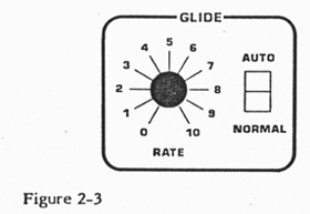
 Fig 2-3
The GLIDE module is a "lag processor." It sets the rate of change for the KYBD CV. When set to zero, the KYBD CV instantly steps between notes. As the GLIDE knob is advanced, the KYBD CV does not step quickly between the notes, but begins instead to "slew" between them.
RATE knob: Determines the rate of glide (portamento) between notes.
NORMAL-AUTO switch: In NORMAL, Glide operates in the traditional manner. In AUTO, the keyboard will glide only when a new key is hit with the previous key still held. This enables complex, "tuned" pitch bending with one hand.
OSC A and OSC B knobs: Set the level of oscillator input to the FILTER.
NOISE/EXT knob: Sets the white noise level input to the FILTER. Noise is an unpitched source useful for effects such as surf, wind or cymbals. When the backpanel external audio input is used, noise is bypassed and this knob sets the level of external signal input to the FILTER.
To get any sound out of the Pro-One, at least one of these three knobs must be turned up (unless the filter is being used as a pitch source).
CM 100 2/81
The FILTER module contains controls for the filter itself and for its envelope generator.
CUTOFF knob: Sets cutoff frequency for the 24 db/octave (4-pole) low-pass filter. It is rather like a tone control. Cutoff is the frequency below which all elements of a signal are let through. The higher-frequency components of the signal (i.e. all those above the cutoff frequency) are suppressed. The higher the knob is set, the higher the frequencies that are allowed through the filter.
RESONANCE knob: Determines the amount of filter resonance. As the setting is increased from 0 to approximately 7 the amount of resonance ("emphasis," "regeneration," or "Q") applied to those signal components at the cutoff frequency will increase. The components far below the cutoff frequency will be less audible relative to the frequencies being resonated. As the setting is increased beyond 7, the filter breaks into oscillation and will act as a sine-wave audio source whose pitch is determined by the cutoff frequency.
ENVELOPE AMOUNT knob: Sets amount (not the shape) of ADSR filter envelope CV controlling the filter cutoff frequency. The filter envelope generator is discussed below.
KEYBOARD AMOUNT knob: Determines the amount of KYBD CV controlling the filter cutoff frequency. When set between 7 and 8, the filter cutoff frequency is maintained at a constant point relative to the notes played on the keyboard, creating consistent tone. When set to 10, notes played higher on the keyboard will have less of their overtones suppressed than those played on the lower end of the keyboard. As a result, the higher notes will have a brighter timbre. When reduced or off, notes played higher on the keyboard will have more of their overtones suppressed than noted played lower. As a result the higher notes will have a duller timbre.
CM 100 2/81
The filter envelope generator contours timbre by controlling the filter cutoff frequency. The entire contour pattern is initiated when a key is struck, producing a GATE. The initial appearance of the GATE "triggers" the envelope generators to proceed through their ATTACK and DECAY periods. After the ATTACK and DECAY periods set for each envelope generator have elapsed, it will produce a steady control voltage (CV) at the level set by the SUSTAIN knob for as long as the GATE is present. When the key is released, the GATE goes off and the envelope generator output voltage drops to zero at a rate set by the RELEASE knob.
ATTACK knob: Varies time for envelope to increase from zero to maximum, from 2 milliseconds to more than 6 seconds.
DECAY knob: Varies time for envelope to decrease from maximum to SUSTAIN level, from 2 milliseconds to more than 6 seconds.
SUSTAIN knob: Varies level from zero to maximum. Remember, this is a level control, not a time control. (SUSTAIN time is the period between the end of the DECAY and when the key is released.)
If SUSTAIN is set at maximum then the DECAY knob setting is irrelevant.
RELEASE knob: Varies time for envelope to decrease from sustain level to zero, from 2 milliseconds to more than 6 seconds. If the key is released before either the ATTACK or DECAY periods have elapsed, this knob controls the time taken for the output to drop to zero from its level when the key was released.
If the ATTACK and DECAY periods have elapsed and SUSTAIN is set to 0, the RELEASE knob setting is irrelevant.
CM 100 2/81
The ATTACK, DECAY, SUSTAIN, and RELEASE knobs in this module shape the envelope applied to the final VCA in the same manner as the corresponding controls in the FILTER module.
Unless the SUSTAIN knob is somewhat advanced, nothing will be heard after the ATTACK and DECAY periods have elapsed.
A synthesizer's expressiveness stands on its modulation facilities. The Pro-One has three modulation sources which are fully mixable and routable over simultaneous WHEEL- controlled or DIRECT paths to five destinations in the voice itself.
Two of the three modulation sources (filter envelope generator and OSC B) were described above. The third source is the LFO.
FREQUENCY knob: Varies LFO range from approximately .1 to 30 Hz.
Waveshape switches: Function identically to OSC B.
CM 100 2/81
[Image rotated 90 deg.]
[Page 22]
FIL ENV, OSC B, and LFO AMOUNT knobs: Determine the amount of modulation mixed into the WHEEL or DIRECT paths by the adjacent ROUTE switches.
FIL ENV, OSC B, and LFO ROUTE switches: Assign the modulation sources to either the WHEEL or DIRECT paths. Each source routed DIRECT is mixed and applied directly to the selected destination, while those routed WHEEL are mixed then sent to the MOD wheel which determines the depth of modulation.
OSC A FREQ, OSC A PW, OSC B FREQ, OSC B PW, and FILTER switches: Select the WHEEL or DIRECT modulation path (or neither) for each destination.
CM 100B 5/81