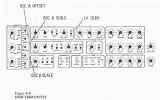
 Fig 4-0
[The Sequential Circuits Pro-One Annotated Manual]
[Annotations in bold square brackets by
jet.]
[Scanned from a photocopy of the original. Original format retained
wherever possible.]
[Modified or replaced graphics noted as such.]
|
SECTION 4 |
ROUTINE MAINTENANCE |
|
|
4-0 |
25 | |
|
4-1 |
25 | |
|
4-2 |
25 | |
|
4-3 |
28 | |
|
4-4 |
28 |
This section covers all maintenance which the player can be expected to perform.
The external metal surfaces and plastic keys can be cleaned with mild soap and water. Don't use alcohol, ammonia, or phosphate-based cleaners. They can remove the paint and ruin the key finish.
This paragraph describes adjustment of the four trimmers accessible through the front panel. All four trimmers interact, so this procedure must always be completed in the order presented. The entire procedure is done by ear, without instruments. What you will be listening for is often described below by the term "zero-beat." This refers to the principle that two pitches near the same frequency produce "beats" at a rate equivalent to their difference. For example, if your ear is presented with two pitches such as 440 (A) and 444 Hz, it will hear also four beatsper- second. As one pitch approaches the other, the number of beats-per-second decreases until they can hardly be counted. This point is called "zero-beat," indicating the two oscillators are tuned to exactly the same frequency (or some harmonic "overtone").
CM 100 2/81
-OSC A SCALE-
1. Patch according to Figure 4-0. Note trimmer names and
locations.
2. Hit C0 and adjust OSC A FREQUENCY for zero-beat.
3. Hit C3 and adjust R128 OSC A SCALE for less than 1 Hz beating.
4. Repeat steps 2 and 3 until no further improvement can be made.
_-1V TRIM_
5. Switch OSC A OCTAVE to 0.
6. Switch OSC B OCTAVE to 1.
7. Hit C0 and adjust OSC A FREQ for zero-beat.
8. Switch OSC A OCTAVE to 3.
9. Adjust -1V TRIM for zero-beat.
CM 100B 5/8 1
-OSC B SCALE-
10. Switch OSC A OCTAVE to 1.
11. Switch OSC B OCTAVE to 1.
12. Turn OSC A FREQUENCY to 5.
13. Turn OSC B FREQUENCY to 5.
14. Switch OSC B KYBD on.
15. Hit C0 and adjust OSC B FREQUENCY for zero-beat.
16. Hit C3 and adjust R148 OSC B SCALE trimmer for less than 1 Hz
beating.
17. Repeat steps 15 and 16 until no futher improvement
can be made.
_OSC A OFFSET_
18. Adjust OSC A FREQUENCY to 0.
19. Switch OSC A OCTAVE to 3.
20. Adjust OSC B FREQUENCY to 0.
21. Switch OSC B OCTAVE to 3.
22. Hit C1. Trim OSC A OFFSET for zero-beat
CM 1 00B 5/8 1
1. Switch power off.
2. Unplug power cord.
3. Remove wooden side panels (2 screws each side).
4. Remove three screws along front edge.
5. Carefully slide top panel assembly forward. When front edge
is clear of keys, lift it up just enough to allow clearance for your
hand.
6. Reach in and disconnect AC power connector running from back panel
to underside of printed circuit board (PCB), at right. (When
reconnecting, orient connector so the side through which you can see
the metal contacts is visible.)
7. Also disconnect keyboard cable from PCB. (When
reconnecting, the keyboard cable should be twisted so that the ribbon
crosses over the board. If correct, the numbers 9-16 stamped
on the connector will run along the PCB edge.)
8. Assembly is just the reverse of these steps.
The fuse must be changed whenever the line voltage is switched (as discussed in paragraph 1-1). A 1/4-amp SLO-BLO fuse should be used for 115V operation. A 1/8amp SLO-BLO fuse should be used for 230V operation.
The fuse should be checked when the Pro-One does not appear to be working (as discussed in paragraph 1-7).
To check or change the fuse, first unplug the power cord then open the case as described above. Lift the top panel assembly off and turn it over. The fuse can be found to the right, mounted to clips on the PCB underside.
CM 100 2/81